FAQ
Why does a permanent magnet AC motor need a VFD?
Why can’t we operate a permanent magnet (PM) AC Motor directly connected to the grid? The grid produces the rotating stator magnetic field at the grid frequency. I suppose the rotor should rotate because its magnetic field is either attracted or repelled by the rotating stator magnetic field continuously at the grid frequency, but why does the rotor just vibrate?
A: Assuming it’s either an IPM or SPM motor, they are synchronous motors and upon start up, the magnets locate themselves. Depending on brand, they will have internal sensors or Hall ICs.
Using an IPM or SPM, you should be aware;
1. Use soft start, PM motor reach full speed/full torque nearly instantly. The shock load often damages connected mechanical components.
2. Voltage must be controlled.
3. You should not run more than 1 motor on 1 variable frequency drive (VFD).
4. VFD capacity must match motor (do not mix a 1hp VFD with a 1/2 hp motor).
Note; a spike can demagnetize the magnets leaving you with an expensive boat anchor.
What is Safe Torque Off in Variable frequency drive?
STO (Safe Torque Off) finds its roots with European manufacturers and has been driven into the foreground by the European safety codes. As of 2017, STO is widely accepted in both the European and Asian markets as a basic safety component. This feature has started to become more prevalent on drives in the US market as newer models of VFD’s are developed and the technology is included.
Since this is not yet a North American requirement most low cost drives are not equipped with this feature, however, that will most likely change as time moves forward.
Now down to the basics…
The STO function is the most basic drive-integrated safety function. It ensures that no torque-generating energy can continue to be applied to a motor and prevents unintentional starting.
Rather than using separate input contactors or safety relays, which require additional installation and maintenance, a VFD with STO can be brought to a standstill in a sufficiently short time. This is done through the load torque or friction and is used when coasting down the drive is not relevant to safety.
STO also allows safer equipment functionality for equipment that has to stop frequently to either be serviced or stopped as part of the production process. This enables safe working when an item, like a protective door, is open (restart interlock) and can be used in wide range applications with moving axes, e.g. handling, conveyor technology.
When is Dynamic Braking Resistor used in VFD?
There are basically three ways to bring a rotating machine to a stop. The first method is to apply a mechanical brake to the system: the problem encounter here is that high-torque systems often exceed the capacity of the brake, requiring some form of slowing down to a more reasonable speed before applying the mechanical approach. The second is to simply “shut off” the power and allow the system to coast down from inertia and friction. This is easy to accomplish … but can take a long time, particularly for high-speed large-mass systems. The third is to apply an electrical “brake” via a regenerative variable frequency drive (VFD) and/or dynamic braking resistor. Essentially, the dynamic braking resistor is a dumping ground for the energy contained in the rotating system, allowing it to be “bled off” as electrical energy. Because the operational mode has changed from motoring (power flow from VFD source to machine) to generating (from rotating machine to VFD), the VFD drive must be capable of supplying power in both directions – i.e. regenerate.
“Controlled” stops are ones whereby the machine is brought down from operating speed to standstill in a fairly rapid manner; as mentioned earlier, this can be accomplished by mechanical means … but larger equipment necessitates the use of electrical (dynamic braking resistor type) braking. The choice whether to have a controlled stop is part of understanding the application and the process.
Is VFD always the best solution?
Choose any centrifugal pump with a full speed duty point flow significantly to the left of the Best Efficiency Point flow. Then, operate that pump in a system with a comparatively high set point pressure (e.g. a single stage centrifugal with a 20m full speed duty point and an 18m static head or minimum set pressure – you could also use 60m/55m and get a similar effect). Then, check the specific energy for that duty point (i.e. the kWhr/kL which, for a fixed total volume pumped, is a firm indication of how much power you will use). Then, simulate the low speed duty and identify the specific energy for that duty point and you will more than likely see a significantly increased kWhr/kL compared to the full speed duty point.
Note that the actual kW value drawn by the motor will probably be lower with the reduced speed. What the increased kWhr/kL value tells you is that the pump will have to run much longer to pump the same volume and this will end up costing your more in energy consumption (i.e. power bill) for the volume that you have to pump. e.g. if your pump uses half the power but runs for 3 times as long to deliver the same volume then you have used 50% more energy and not saved 50%.
Inverter duty motor vs Standard motor on VFD
If 2 pole 50 hz standard motor run with 4:1 ratio what will be temperature rise expected?
And
if 2 pole 50 hz inverter duty motor runs with 4:1 ratio what will be temperature rise expected? Like “inverter duty motor will give 4 time life then standard motor?”
I know that you can use inverter duty motor with 10:1 ratio. while standard motor 2:1. I know VFD (variable frequency drive) operating range for positive displacement Pumps. Positive displacement Pumps never use Inverter duty motor even to getting a ratio 5:1 with 4 pole motor. Instead they prefer to use reduction drive, which decrease the overall efficiency of system and add extra cost.
Temperature rise is the difference between the ambient and the hot winding temperature. A motor with a 1.15 SF and class F insulation (for 1500 Hp and less) is rated at 125C per NEMA MG-1. Class A insulation is rated at 80C and class B is 100C. You can ask for an embedded detector in the motor to monitor the motor temp.
To calculate motor temp rise, hot winding temp needs to be known and there is a formulae that involves hot temperature, cold temperature, hot resistance, cold resistance and a K constant (234.5) for copper.
Motor manufacturers classify their motors as inverter duty when they use a class F insulation. Will it give 4 time more life time than standard class A or B? Not really. They wind their motors per NEMA MG-1 classification.
The number of poles shouldn’t have anything to do with it. You can vary a 6-pole motor just as easily as a 2-pole. You just get a different speed range out of the shaft. You can even go over speed. I’ve run regular induction motors at 75 hz before. With proper engineering attention, you can go a lot higher.
Why do some VFDs need reactors?
There are two types of reactors used with VFDs: load reactors (or DC bus chokes) and AC line reactors.
The goals of these reactors are to reduce the harmonic content of the input current (improve distortion power factor) and to reduce the conducted EMC noise on the supply.
Some VFDs have either of these reactors built in as standard, and others don’t . The variable frequency drives that don’t include the reactors are smaller and cheaper, but may require them to be mounted separately in order to comply with CE or similar EMI/EMC regulations.
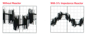
Look at the input current waveform through an oscilloscope (see image below). You will notice that it’s made up of short high-amplitude current pulses on the crest of the waveform (left). This is due to the capacitive-input filter. The addition of the reactor will stretch these pulses (right).
Variable Frequency Drives application site inspection
- Compare the torque characteristics of constant, variable & shock loads.
Explain the function of reactors that are connected in series with the line & load side of a variable frequency drive.
3. List the factors that need to be taken into account in selecting the location for a VFD.
4. What is the purpose of a variable frequency drive enclosure?
5. What is the function of a VFD’s operator interface?
6. How are the effects of electromagnetic interference minimized in a variable frequency drive installation?
7. In addition to line losses, why must cable lengths between a PWM VFD & motor be kept to a minimum?
8. Why is proper grounding required for the safe & reliable operation of a variable frequency drive system?
9. A bypass contactorworking in conjunction with an isolation contactor is utilized in certain variable frequency drive installations. What purpose is served by this combination of contactors & how do they work together to achieve this?
10. Outline the basic code requirement for a VFD’s controller & motor disconnecting means.
11. Summarize the types of built-in protective functions that can be programmed into a VFD.
12. Compare the operation of dynamic, regenerative, & DC-injection variable frequency drive braking systems.
13. Ramped acceleration & deceleration are two key features of variable frequency drives. Give a brief explanation of how each is achieved.
14. Compare digital & analog input & output VFD control signals.
15. List typical preset functions that digital inputs may have assigned to them.
16. Why is forward/reverse interlocking not required on variable frequency drives?
17. Compare the manner in which the control logic is executed in a hard-wired electromagnetic starter & a variable frequency drive.
18. Explain the term dry contact as it relates to a VFD’s relay output.
19. List typical motor nameplate data that may be required to be programmed into the variable frequency drive.
20. Explain the term derating as it applies to a variable frequency drive & list factors that might require a VFD to be derated.
21. Compare PWM, VVI, & CSI VFDs.
22. Outline how setpoint speed is maintained in a PID control loop.
23. Explain the term parameter as it applies to the variable frequency drive.
24. List several common adjustable parameters associated with VFDs.
25. What is the difference between program & display parameters?
26. What potential safety hazard is associated with DC bus capacitors?
27. When LEDs are used for problem indicators, what does a steady glow indicate compared to a flashing one in the variable frequency drive?
28. Compare the operation of autoreset, nonresettable & user-configurable fault parameters.
29. Explain the term fault queues as it applies to variable frequency drives.
Can I improve the VFD waveform without using output filter?
The output waveform as seen on an oscilloscope does not look very sinusoidal when it come to the voltage. If one looks directly at the motor current you will see a sinusoidal waveform. What happens in the variable frequency drive (VFD) processor it runs an algorithm to approximate the voltage and the torque regulator controls the motor current directly. As for improving the waveform produced by the VFD the best way is to use some type of filter on the output. It could a simple line 3 phase line reactor (3%) similar to the input line reactor. One could design an LC type filter to put on the VFD output. If you chose to design the LC filter be sure to take in account the modulation frequency of the IGBT. Modulation frequency could be between 2 kHz to 16 kHz.
Inverter duty motors are designed specifically to accept the less than perfect waveforms to a certain level. That level is a combination of the particular VFD being used, the motor and the cable length/capacitance of the system. The only case where a minimum output reactance is needed is when multiple inverters are paralleled (to act as a single, higher power unit).
The line reactor solution is an easy solution using something off the shelf. Size the line reactor for the expected full load voltage and current at 50/60 hertz. You should be using a 3% reactor something like (11 kw to 15 kw 0.45mH 33A). Particularly if the motor leads are 40 meters or longer. Hope this helps. VFD and AC motors seem so simple but yet are so complex.
What Types of motors can be used with variable frequency drives?
The various types of industrial motors that can be used with variable frequency drives are:
- Dc motor: dc motors are still in production although the number of active manufacturers has decreased considerably, specifically those that are still manufacturing large dc motors (> 1 MW).
- Ac asynchronous squirrel cage motor: This type of motor is the most commonly used motor in industrial processes with variable frequency drives.
- Ac asynchronous wound rotor motor: This type of motor was traditionally used in variable frequency drive when the load required a high starting torque and the strength of the power supplynetwork was insufficient to permit Direct On-Line (DOL) starting. Variable speed operation is obtained by varying the effective resistance in the rotor circuit.
- Ac synchronous motor with brushless ac or brushed excitation.
- Ac synchronous motor with permanent magnet excitation: This type of motor is specifically designed for operation with a variable frequency drive. Synchronous motors are used mainly in the high power ranges to minimize costs by minimizing the current rating of the variable frequency drive and due to the non availability of squirrel cage induction motors.
The most common electrical VFD used in industry today is the variable frequency drive using Voltage Source Inverter (VSI) typology and controlling asynchronous squirrel cage motors.
The power range of ACS types of variable frequency drives extend from fractional kW such as 0,18 kW to 2 000 kW in the low voltage range and from 200 kW through to 30 MW in the medium voltages. The low voltages that are of interest to the local market are the standard IEC (International and Electrotechnical Commission) voltages namely 230 V single-phase, 400 V three-phase, and 690 V three phase, all at the 50 Hz input frequency. To satisfy the 525 V market, variable frequency drives with a rated voltage of 600 V and 690 V are used. At the medium voltage level the voltages of interest are 3 300 V, 6 600 V and 11 000 V. Economics should be the determining factor as to the rated voltage of the drive given the required power rating, although this is not always the case.
What is the best method to check and test VFD?
Assuming it’s a voltage-source PWM type inverter, run the variable frequency drive without any load at all and look at the VFD output voltage waveform across each of the three phases with a properly rated oscilloscope. If that looks OK, hook up an unloaded motor and run that, again checking the VFD output waveform with a scope. Check the VFD current balance on all three phases. If it looks good and sounds good, it most probably is good. THEN verify that all the VFD inputs and outputs do what they’re supposed to.
How to reduce VFD controlled motor noise?
For many variable frequency drives (VFD), harmonic switching noise can be coupled out of the variable frequency drive power input into the building power wiring. Once harmonics are coupled into the building power, they can appear on sensitive equipment throughout the building. This problem may be made worse by a variable frequency drive with a poorly designed input filter and a small number of switches between the input AC and the DC link.
Incorrect grounding of the motor to the variable frequency drive will allow the system to act as a noise transmitter. I suggest a slightly different grounding method to eliminate the noise problem. An appropriately sized grounding conductor installed in the same raceway as the phase conductors with one end terminated in the motor doghouse and the other end terminated at the grounding terminal of the variable frequency drive. Splices or compromises in conductor integrity are NOT allowed anywhere along the length of this conductor. Bonding of enclosures along the raceway to the motor should use a separate grounding conductor which is used in a typical fashion. The variable frequency drive then needs another grounding conductor back to the power source. After this grounding activity is completed the only other item that may need changing is carrier frequency. Large variable frequency drive driven motors are usually easier to quiet down than the small fractional ones.
To reduce the VFD-controlled motor noise it should be to increase switching frequency if the cable length between the motor and variable frequency drive is short. But If the cable long and there is noise it should be to install du/dt on sine wave filter and make the switching frequency according to the filter specification.
An appropriate filter on the variable frequency drive power inputs, designed to eliminate input switching harmonics resulting from the variable frequency drive AC to DC input switching, may help eliminate the problem. It may be less expensive and easier to place the audio equipment on some form of filtering, like a true double conversion UPS, which would significantly reduce the variable frequency drive (and any other source) harmonics from the audio equipment.
A dV/dT filter smooths the VFD outputs waveform greatly because the primary component in the filter is an inductor. The filter might be a bit noisy, but the motor will be quieter. Because a dV/dT filter or a sine-wave filter are LRC (inductive-resistive-capacitive) circuits, the VFD carrier frequency needs to be fixed at a point or span that will not cause resonance in the filter circuit.